
The Institute of Electrical and Electronics Engineers (IEEE) terminology defines a LINK BOX as:
“A box in which bonding or grounding connections or both are made through Removable (disconnectable) links and which may also contain Sheath Voltage Limiters (SVLs)."
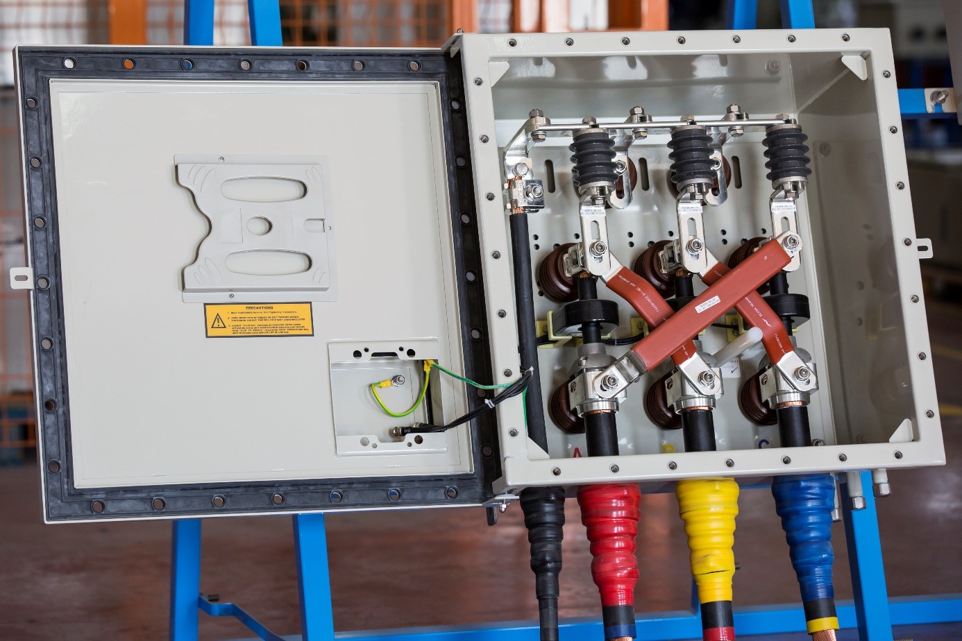
Technically better known as “Disconnectable Link Box" for its sound design and construction features are a High Voltage Underground (buried) Power Cable System accessory. It is an integral part; mechanically and electrically connected to “Sheath Bonding Design Circuitry” of High Voltage underground Power Cable System.
Link Box is electrically and mechanically one of the integral accessories of HV underground cable Bonding System, associated with HV XLPE power cable system.
Sheath Bonding is very essential both commercially and technically to safeguard / protect the cable system against transient over voltages and prevention or greatly reducing of sheath losses.
Bonding System is designed that the cable sheaths are bonded and earthed / grounded in such a way as to eliminate or reduce the circulating sheath currents and to limit standing induced sheath voltages for human safety, and also during any internal fault or short circuit of the system, short circuit current flows directly to the earth through link box.
Link boxes are manufactured basically as three different bonding designs classified as:
The design classification is dictated by Link Box installation along the Power Cable route as indicated on the Sheath Bonding Scheme Circuitry Diagram.
It’s location as indicated on bonding circuitry dictate the internal design construction of copper bar configuration details of the Link Box.
There are also three TYPES depending on how and where they are installed, namely;
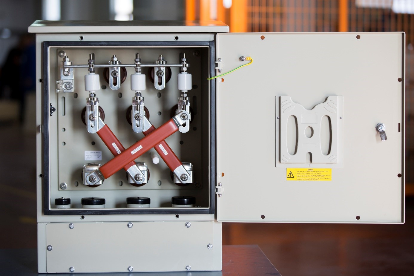
Generally Link Box implies close association with insulated joints (interrupted sheathing design) of a long power line serving as a protective housing safeguarding all the related bonding linkages and components for long reliable service life. They are also installed at both ends of a circuit connected to terminations. At each point, electrically the internal design configuration and installed components are different serving a definite bonding purpose. The internal connections / links are of easily removable design, which can be easily removed; thus allowing disconnecting the individual cable sheaths for Sheath fault testing, establishing the integrity of sheath; that is no cracks / cuts or holes as a result of mishandling during cable laying.
EMELEC is a manufacturing company has all the engineering background and the experience to do the design work of accessories, production capabilities of components and parts per EM design specifications, and the required capabilities geared to do high quality assembly of LINK BOXES.
Key manufacturing processes of Link Box such as cutting, bending and welding are all applied in our production field. Computer based machining used in each stage of production to achieve tolerance of the critical dimensions.
